I. Fault Background & Phenomenon
In early June, during cargo discharging operations at Qinhuangdao Port, a core bulk cargo hub in northern China, the auxiliary diesel engine of our long term client’s bulk carrier suffered an unexpected startup failure. The shutdown disabled the ship’s ballast pumps and hatch cover actuators, halting terminal cargo discharge. This created risks of hefty demurrage charges and vessel port delay losses for the client. After repeated self-inspections by the ship’s on-board maintenance crew failed to resolve the startup fault, our team urgently dispatched a senior electrical engineer to board the vessel for emergency repair.
Board the vessel, got the summary from ship crew as below:
Core Fault Symptom: Complete Failure to Start the Engine
When pressing the START button on the MEC24-H control panel, the pre-lubrication pump and fuel valve actuated normally. (The peripheral auxiliary control circuit composed of IO modules and relays functioned properly, as this circuit operates independently of the ECU.)
However, the engine produced no fuel injection and showed zero ignition or startup response. The crankshaft speed sensor transmitted standard AC speed signals to the ECU input terminals, yet the ECU failed to output any fuel injection drive pulses.
II. Systematic Step-by-Step Troubleshooting Procedures
Step 1. Fault Boundary Identification – Distinguish Faults in Peripheral Wiring/Sensors vs. ECU Hardware
This stage adopts low-cost measurement methods to rule out basic wiring faults, avoiding premature diagnosis of ECU damage that leads to unnecessary spare part waste and prolonged vessel downtime.
1.1. ECU Power Supply & Ground Circuit Inspection Criteria
(1) 24V power pins on the main connector: Stable voltage shall range from 23V to 26V under no-load and loaded conditions;(voltages below 22V will directly trigger ECU operational malfunctions. )
(2) Ground pin resistance standard: Less than 0.5Ω to ground. (Excessive measured resistance indicates rust, oil contamination or loose connections at grounding points, resulting in signal distortion and abnormal voltage drop. )
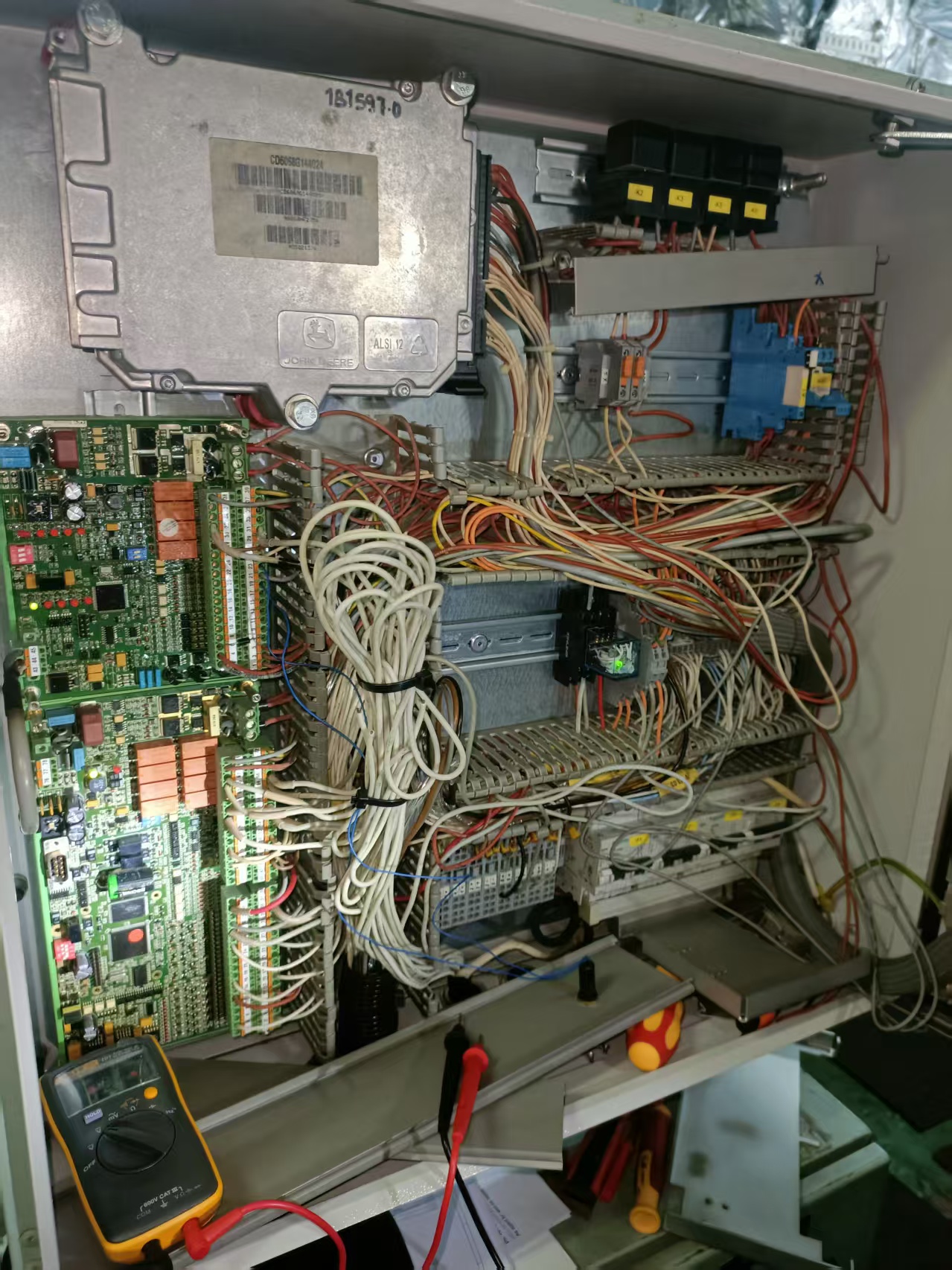
(3) A dedicated ECU power fuse is installed on the blue DIN rail fuse holder on the right side of the electrical control box. Verify fuse integrity via visual inspection and continuity testing--- All in order
( If a new fuse blows immediately after replacement, an internal short circuit within the ECU is confirmed.)
1.2. Transmitter Bypass Simulation Test (Validates Only Front-End IO Circuits)
Disconnect wiring terminals of lube oil pressure and cooling water temperature transmitters, then connect an external 4–20mA standard signal generator to the orange spring terminals of the IO board. Input standard analog signals of 4mA, 12mA and 20mA respectively:
(1) Found readings on the MEC24-H panel change synchronously with the signal generator: The transmitters and front-end IO acquisition wiring are intact, Such behavior allowing quick elimination of sensor faults.
(2) This test only covers front-end IO wiring and cannot verify the integrity of internal ECU acquisition channels.
(3) To test ECU analog acquisition channels, disconnect the CAN bus and feed standard current signals directly to the ECU analog input pins, then retrieve underlying ECU data for judgment.
1.3. CAN Bus Communication Resistance Test
Quickly identifies three types of communication faults: CAN wire breakage, short circuit and missing termination resistors, to divide fault areas:
(1)Abnormal bus resistance: Fault localized to CAN wiring or connectors.
(2)Stable bus resistance of 60Ω: Wiring remains intact, with the root cause traced to a damaged internal CAN transceiver chip inside the ECU.
Supplementary Fault Logic Explanation
The crankshaft speed sensor is hardwired directly to the ECU via an independent circuit; CAN bus faults do not interfere with speed signal collection. Instead that the unique fault behavior observed: the ECU received normal speed pulses but could not receive startup enable commands issued by the MEC24-H panel, locking all fuel injection output.
There are two independent root causes for loss of fuel injection:
A. Damaged CAN bus wiring: Interruption of upper-layer startup command transmission (wiring fault with low repair costs).
B. Severe internal ECU hardware damage: Failure of the CPU, fuel injection drive module or CAN transceiver chip, requiring expensive genuine replacement of the complete ECU assembly.
Here the method of Measuring CAN termination resistance is a low-cost preliminary operation to rapidly differentiate these two fault categories, preventing spare part waste and extended downtime caused by misdiagnosis.
Additional Fault Severity Classification
If only the CAN transceiver chip burns out, only upper-layer communication is lost; the engine can still inject fuel when communication signals are manually bypassed.
But at present The vessel’s fault involved normal speed input yet complete loss of injection output, which cannot be explained by sole CAN chip damage. Subsequent inspections were required to confirm compound hardware failures of the main CPU and fuel injection drive module.
CAN-H / CAN-L Wiring Measurement Standards (All connectors fully engaged, power completely cut off from the unit before testing)
(1)Standard parallel resistance between the two lines: Approximately 60Ω (two 120Ω termination resistors installed at both device ends in parallel).
(2)Resistance measured from a single disconnected connector: Standard 120Ω per individual unit termination resistor.
(3) Fault judgment criteria: Resistance far below 60Ω = CAN bus short circuit; 120Ω measured with all connectors engaged = loose connector at one bus end or broken wiring midway.
(4)In this repair case, measured bus resistance was fully normal, yet the MEC24-H continuously triggered an ECU communication loss alarm, confirming failure of the ECU’s internal CAN communication chip.
Step 2. Retrieve Underlying ECU DTC Fault Codes (Core John Deere Electronic Control Diagnostic Reference)
Access original factory fault codes via the MEC24-H operation menu to grade hardware damage severity:
(1) Fault Code P0606: Internal Control Unit Fault, signifying irreversible hardware damage to the ECU motherboard CPU and memory chip, often accompanied by total communication loss and failure of multiple acquisition parameters.
(2) Power Cycle Reset Verification Test: Disconnect the ECU’s 24V positive power supply and negative ground cable, then leave the system powered off for 10 minutes to discharge residual capacitance on the board.
(3) Re-energize and clear fault codes. Found P0606 reappears within seconds after power-on, permanent ECU hardware damage is confirmed, rather than temporary program disturbance caused by voltage fluctuations.
Step 3. Actual Measurement of ECU Input & Output Signals to Rule Out False Fault Codes
Must noted that Extreme cabin conditions including high temperature, vibration and voltage drop, together with poor ground connections, may trigger false P0606 alarms in the ECU.
This step implements full-circuit cross-verification of all signals to eliminate external interference and confirm inherent ECU hardware failure.
1. Input Side Signal Inspection (Speed, Temperature & Pressure Analog Signals):
Use a multimeter and oscilloscope to verify normal transmission of AC crankshaft speed signals and 4–20mA analog signals from temperature/pressure transmitters to corresponding ECU pins.
Found : The ECU fails to recognize valid input signals and repeatedly logs signal out-of-range faults, the internal signal acquisition and processing circuit is damaged.
2. Output Side Drive Signal Inspection (Fuel Injection & Speed Governing Modules):
Under engine startup conditions, measure ECU fuel injection drive output pins with an oscilloscope.
Found: No fuel injection pulse voltage is detected and external fuel injectors plus wiring paths remain intact, the internal ECU fuel injection drive power module is burned out.
Critical Reminder:
Ordinary digital multimeters with DC voltage settings feature insufficient sampling rates to capture millisecond-level startup injection pulses, easily leading to false judgments of “zero output”.
Prioritize oscilloscopes or fuel injector pulse test lights (Noid Lights) to inspect fuel injection drive outputs.
Step 4. Visual ECU Disassembly Inspection + Cross-Swap Test (Our Recommend Final Fault Confirmation Method)
(1) Remove the ECU’s silver metal shielding housing and visually inspect the PCB circuit board. Seriously Water stains directly confirm hardware damage.
(2) Cross-swap Test with Identical Unit (Most Accurate Confirmation Method): Replace the faulty ECU with a matching genuine John Deere ECU retrieved from ship spares .
(3) After replacement, auto-stop alarms disappeared, temperature and pressure readings returned normal, and all engine startup, shutdown and fuel injection actions operated flawlessly, 100% verifying complete hardware failure of the original ECU and complete this time trouble shooting matter
Supplementary Notes for Two Distinct Fault Scenarios
(1) When P0606 reappears immediately after power reset:
Abnormal signal recognition and absent injection pulses detected in Step 3 are secondary faults derived from main CPU damage. The root failure is already confirmed via ECU power-on self-test codes, and signal measurements serve only as supporting documentation for complete repair records.
(2) If P0606 never triggers throughout inspection while signal recognition faults or loss of injection output persist: Only partial ECU acquisition circuits or fuel injection drive power modules are burned out, with intact main CPU and memory chips, which does not constitute irreversible damage to the full internal control unit.
III. Emergency Handling & Repair Solutions for Damaged ECU Hardware
1.For confirmed ECU hardware failure, repeated forced engine startup is strictly prohibited. Failed ECU logic control causes insufficient lubrication and excessive cylinder temperature, easily inducing severe secondary mechanical faults such as cylinder scoring and crankshaft seizure.
2. Marine John Deere ECUs are preloaded with factory-exclusive engine calibration parameters and cannot be disassembled or repaired on-site. Two viable solutions are available: send the unit to a professional marine electronic control repair station for chip replacement and recalibration, or purchase a brand-new matching full ECU assembly.
3. After ECU replacement, re-match basic engine parameters and clear all historical fault codes via the MEC24-H interface. Complete a 30-minute combined no-load and loaded test run to confirm elimination of auto-stop alarms before returning the engine to operational service.
4. Friendly remind for more sharing about automation troubleshooting matter which we had experienced :
(1) When troubleshooting abnormal shutdown and alarm faults of marine auxiliary engine ECU onboard bulk carriers, we have accumulated abundant on-site overhaul experience at multiple domestic coastal ports.
For automated control system failures of hatch covers, we have completed full-circuit diagnosis and component replacement work, refer to our case: <Overhaul of Hatch Cover PLC for Bulk Carrier at Zhoushan Port>
(2) Abnormal power supply from the generator set will also trigger secondary fault codes of the auxiliary engine ECU. Once we responded to an urgent breakdown request at Lianyungang anchorage: <Emergency Repair of Generator for Bulk Carrier - Lianyungang》
(3) In addition to power and logic control modules, remote monitoring failures of boiler automatic systems often interfere with the normal signal transmission of the whole vessel’s electrical network. You can check our related maintenance record: <Malfunction of Boiler Remote Control System on Dalian Oil Tanker>
(4) For daily long-term monitoring and regular calibration of cargo hold measuring equipment to avoid hidden electrical hazards, our routine maintenance guide is available here:< Daily Maintenance of Cargo Hold Tank Gauging System>
IV. Industry Technical Summary & Operation & Maintenance Reflections
Marine equipment faults often feature overlapping superficial symptoms and deep root causes, with routine malfunctions alternating with rare complex failures. Reliance solely on past operational experience creates diagnostic limitations. Troubleshooting must adopt systematic, divergent verification thinking to continuously narrow the fault scope, even when the root cause cannot be located rapidly.
As vessel automation integration advances, electronic control systems and intelligent terminals interconnect an increasing number of auxiliary devices. While reducing daily maintenance workloads, this trend places higher demands on marine engineers’ professional knowledge reserves and standardized systematic troubleshooting logic.
The core approach to simplifying complex electronic control faults lies in fully mastering equipment hardware structure, complete control logic, standard operating procedures and periodic maintenance requirements. Comprehensive familiarity with equipment performance allows early identification of hidden hazards and implementation of preventive maintenance before faults escalate. Thorough command of on-board equipment improves cabin operational safety and builds greater confidence to address sudden port malfunctions and harsh sea conditions.



 +8615005328513 (wechat ) +8613606393913 (Whatsapp)

 No. 8888, Huangshan Road, Huangdao District, Qingdao City, Shandong Province, China.