Urgent Troubleshooting of Bulk Carrier Generator at Lianyungang Port | Resolution of Generator Load Capacity Failure and Cargo Handling Power Faults
Urgent assistance was requested by the client:
-
Their bulk carrier berthed at Lianyungang Port suffered severe generator speed fluctuation and frequent fault alarms, meanwhile the generator lost most of its load capacity, and repeated power failures of cargo handling equipment triggered constant complaints from the port side.
-
The malfunction seriously hindered loading and unloading operations and risked shipping schedule delays. Failure to resolve the issue timely would lead to heavy losses including berthing fees and compensation claims.
-
In response to the urgent repair demand, we immediately dispatched experienced engineers to the ship. They were requested to cooperate closely with onboard staff, consult official equipment manuals and historical fault records, professionally analyze abnormal operating symptoms, accurately locate the root cause and complete troubleshooting efficiently.
Part I:On-site Fault Investigation & Preliminary Assessment
Our engineers communicated with ship personnel immediately after boarding to clarify symptoms and potential causes, and formulated a preliminary troubleshooting plan.
1.1 Fault Symptoms
(1) Periodic speed fluctuation:
The rotating speed rises and falls regularly under no-load and loaded conditions. Causing the governor actuator operates repeatedly with obvious mechanical adjusting noise.
(2) Abnormal response under load variation:
The speed fails to recover timely when load changes, triggering frequent over-speed and under-speed alarms with poor operational stability.
(3) Insufficient load capacity at full stroke:
Even when the accelerator lever reaches maximum travel, the generator cannot operate at full load, and speed drops sharply once loaded.
1.2 Potential Fault Causes in doubt from ship crew :
(1) Internal wear of governor ,improper parameter setting and limited actuator stroke
(2) Sticking servo valve, unstable fuel pressure and worn fuel pump if possible
1.3 Troubleshooting Strategy
-
Potentiometer converters are easily overlooked vulnerable components in governor systems of aged vessels. but the distorted position signals will disrupt the entire closed-loop speed control.
-
Here we recommend prior inspection of the converter serves as the most efficient and cost-effective way to eliminate unstable rotation and frequent alarms.
-
Other components including governor, servo valve and fuel supply system will be checked subsequently if no fault is found in the converter.
Part II: On-site Maintenance Implementation
2.1 Basic Parameters of the Equipment
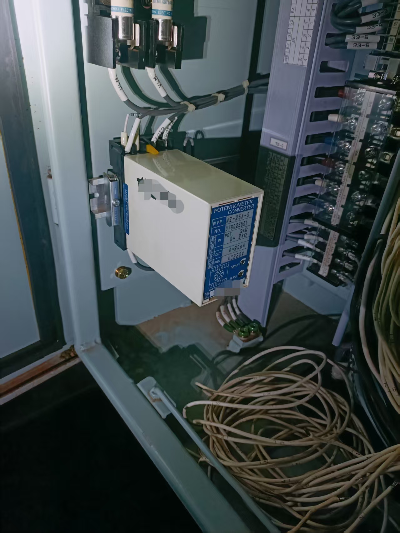
The faulty unit is Watanabe WVP series potentiometer converter, model WVP-NZ-25A-5, a core signal conversion device for ship automatic control
.
-
Input signal: 0~2kΩ potentiometer resistance signal
-
Output signal: 4~20mA standard current signal
-
Power supply: AC220V
Found the Zero and span adjustment knobs are equipped to calibrate output signals and ensure accurate correspondence with actual mechanical travel.
2.2 Visual Inspection & Mechanical Check
2.2-1 Terminal inspection after power cut
(1) Check all input, output and power terminals for looseness and oxidation. Vibration in engine room often causes poor contact and intermittent signal transmission.
(2) Special attention shall be paid to shielding cables of 4-20mA signal circuit, ensure Single-end grounding shall be guaranteed to avoid signal jump caused by electromagnetic interference.
2.2-2 Accelerator potentiometer mechanical inspection
(1) Push the accelerator lever manually to confirm smooth movement and tight connecting bolts.
(2) Measure resistance variation with a multimeter. Resistance shall be close to 0Ω at full close position and 2kΩ at full open position.
(3) Steady and continuous resistance change without sudden jump indicates intact potentiometer. Abnormal resistance means immediate replacement is required.
At last found No defect in mechanical structure and external wiring, while the original faults persist. It is judged that signal deviation and zero-span drift lead to the malfunction, thus signal comparison test is conducted.
2.3 Signal Comparison & Fault Location
(1) Input resistance measurement:
Test input resistance under shutdown and no-load state. The resistance shall match accelerator travel precisely, with approximately 1kΩ at 50% stroke. The input signal is verified normal.
(2) Output current measurement: Connect the multimeter into 4-20mA output loop and record current values at different strokes:
-
7mA at full close position, exceeding standard 4mA, indicating zero drift
-
17mA at full open position, lower than standard 20mA, indicating insufficient span
-
Severe linear distortion appears in intermediate travel, showing abnormal current output
(3) Fault Conclusion
Normal input resistance but deviated output current confirms the fault originates from zero-span drift and performance degradation inside the potentiometer converter.
(4) Fault corresponding consequences:
-
Zero drift → periodic generator speed fluctuation
-
Linear distortion → slow governor response and frequent speed alarms
-
Insufficient span → restricted accelerator travel and poor load capacity
2.4 Zero & Span Calibration
Precondition: Ensure smooth mechanical travel without jamming and looseness at first
(1)Zero calibration:
Set the accelerator to full close position. Adjust ZERO knob to stabilize output current at 4.00mA within tolerance of ±0.05mA.
(2)Span calibration:
Set the accelerator to full open position. Adjust SPAN knob to stabilize output current at 20.00mA within tolerance of ±0.05mA.
(3)Linear verification
Verify current values at 25%, 50% and 75% stroke, corresponding to standard 8mA, 12mA and 16mA respectively. Re-calibrate zero and span if deviation exceeds ±0.1mA until linear performance meets requirements.
(4) Post-repair verification
-
All faults including speed fluctuation, alarms and insufficient load capacity are eliminated after calibration, and the generator restores normal operation.
-
Governor, servo valve, fuel pump and fuel pressure related faults are excluded. Accurate fault positioning cuts maintenance cost and downtime effectively.
Part III: Operation & Maintenance Experience Summary
(1) Replacement criteria for faulty converter
Replace the device directly if the following phenomena still exist after calibration:
-
No or discontinuous current change during knob adjustment;
-
Repeated parameter drift after short-time operation;
-
Irregular jumping of output current.
(2) Attention to hidden vulnerable components
-
Potentiometer converters tend to be ignored in daily inspection, yet they undertake critical signal feedback tasks.
-
Incorrect signals will cause misoperation of the whole governor system.
-
Most speed instability faults are derived from small signal components rather than main governor assemblies.
(3) Standard troubleshooting procedure
-
Adopt the principle from simplicity to complexity and exterior to interior.
-
Inspect wiring and mechanical parts first, then internal control circuits.
-
Check vulnerable accessories prior to precise core equipment to avoid unnecessary maintenance loss.
(4) Additional recommendation for below troubleshooting matter:
When dealing with sudden generator shutdown at sea, you also need to master complete control cabinet inspection procedures.
Refer to our Marine generator control cabinet troubleshooting guide to eliminate hidden circuit risks thoroughly.
For long-term stable operation of the power system, regular inspection of all electrical components is essential.
Check out our full breakdown in Ship generator power distribution panel routine maintenance steps.
If the shutdown failure links back to main engine signal anomalies, read our professional case: Main engine ECU emergency fault diagnosis for bulk carriers.
Part IV: Write at the end (friendly remind )
Over years of maintenance work, we have witnessed numerous cases where minor faults of inconspicuous small components lead to paralysis of marine power and hydraulic systems.
This severely disrupts vessel berthing, departure and cargo handling operations, and may even trigger serious accidents such as ship collisions and marine pollution.
The output fault of the potentiometer converter in this case serves as a typical example. Regular zero and span calibration during daily maintenance could have completely prevented this generator malfunction.
It reinforces our persistent philosophy that proper routine maintenance effectively avoids major equipment failures. More daily inspection and upkeep can prevent systemic breakdowns, eliminating the need for sophisticated repairs and lengthy troubleshooting lasting days or even longer.
The heroic deeds in harsh situations are merely romantic ideals. In reality, vessels can hardly sail safely amid violent sea conditions without careful, standardized daily maintenance. Diligent and earnest routine work is far more valuable than helpless remedies when dangers strike.


 +8615005328513 (wechat ) +8613606393913 (Whatsapp)

 No. 8888, Huangshan Road, Huangdao District, Qingdao City, Shandong Province, China.