Emergency Repair of Main Ballast Pump VFD System on 180,000 DWT Bulk Carrier, Tianjin Port | Guaranteed On-Time Departure & Normal Ballast Operation
On May 28, Xingang Bulk Cargo Terminal of Tianjin port. A 180,000 DWT bulk carrier suffered an unexpected failure of the main ballast pump variable frequency drive (VFD) system during ballast water operation prior to departure upon completion of discharging operations. Tripped by overcurrent protection due to pipeline load fluctuation, the system shut down abruptly, interrupting vessel draft and stability adjustment and delaying the ship’s departure schedule.
Upon receiving the shipowner’s urgent request, our professional technical engineers rushed to the vessel with a full set of maintenance equipment for emergency repairs. We strived to troubleshoot the fault promptly so as to help the shipowner avoid potential hazards and economic losses caused by equipment outage.
Part I: On-board Communication, Failure Condition Analysis and Maintenance Plan
After boarding the vessel, our team held in-depth discussions with the ship’s crew to sort out the whole failure process, preliminarily determine the fault orientation and formulate a dedicated maintenance plan.
This incident also exposed mismatches between the frequency conversion control logic of the ballast system and actual pipeline operating conditions.
(1) Inherent Disadvantages of Marine VFDs (Harsher Operating Environment than Onshore Units)
It's true that Marine equipment operates under extremely tough conditions, which is the key reason why marine VFDs have a higher failure rate compared with land-based counterparts:
(1.1)Harsh ambient conditions:
Continuous vibration generated during navigation and operation tends to loosen wiring and cause component cold solder joints. High humidity and oil contamination inside the engine room corrode circuit boards and motor coils, while dust easily block heat dissipation air ducts.
(1.2)Severe operating loads:
Marine pumps generally work with frequent start-stop cycles and heavy load impacts. The main ballast pump involved in this fault runs continuously under variable loads, keeping the VFD operating at high load for prolonged periods, which makes overcurrent and overheating alarms highly likely.
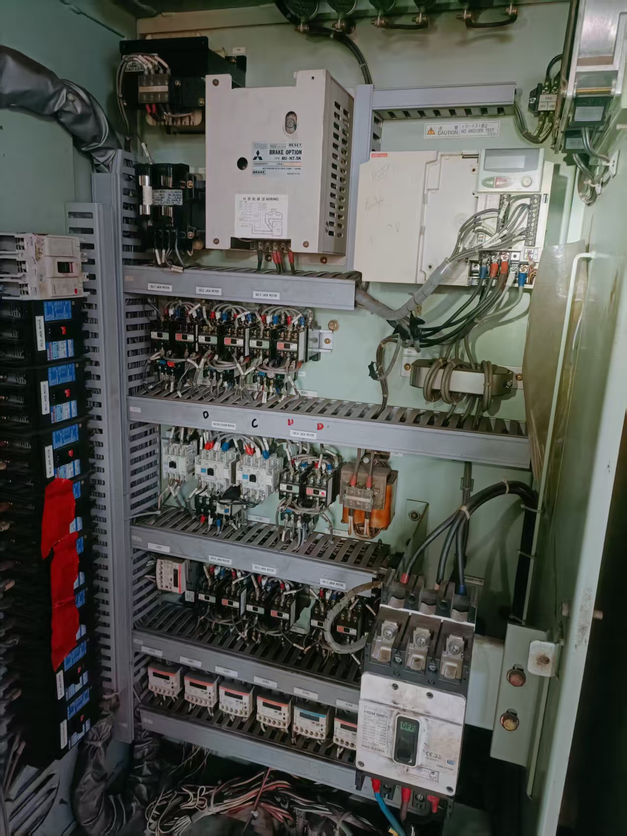
(2) Main Components of the VFD Control Cabinet
This vessel is equipped with a Mitsubishi VFD control system. Its core components are listed below. Combined with the alarm records, the Mitsubishi main VFD unit was confirmed as the key inspection target:
(2.1) Mitsubishi Brake Unit (BRAKE OPTION): Auxiliary braking component matched with the VFD
(2.2) Mitsubishi Main VFD Unit: Core device for motor speed regulation, commonly troubled by overcurrent, overvoltage and overheating alarms
(2.3) Contactor and Thermal Relay Assembly: Components for main circuit switching and overload protection
(2.4) Fuses and Terminal Blocks: Devices for power protection and control signal transmission
(3) Overall Maintenance Procedures
In accordance with marine electrical maintenance specifications and based on the equipment configuration as well as overcurrent and overheating alarms, the work was carried out in four standard phases:
Fault Lockout & Tracing → Hardware Circuit Inspection → Parameter & Logic Verification → System Optimization & On-load Commissioning
Part II. Detailed Troubleshooting and Implementation Procedures
(1) Fault Lockout & Tracing
We strictly complied with marine electrical safety regulations.
1.1 Power disconnection, lockout, tag-out and voltage testing were implemented on the main ballast pump VFD. The control cabinet was opened only after confirming that both the main circuit and control circuit were fully de-energized
1.2 Data retrieved from the VFD historical log indicated an OC (Overcurrent) fault code. The three-phase instantaneous current peak reached 1.8 times the rated current, far exceeding the preset protection threshold. Operation records showed the fault occurred during rapid discharging ops of ballast tanks.
1.3 Two root causes were concluded after comprehensive analysis:
(1)Changes in vessel draft and trim during discharging and ballasting operations led to varying local pipeline resistance, resulting in stepwise load fluctuation of the ballast pump.
(2)The factory-set acceleration and deceleration time was too short. Current surges generated at start and stop, superimposed with pipeline load fluctuation, directly triggered the overcurrent protection.
(2) Hardware Circuit Inspection
Following the principle of hardware prior to software, high voltage prior to low voltage, we first eliminated faults of physical components, circuits and loads to avoid ineffective commissioning and rework.
2.1 Heat dissipation system inspection: Thoroughly cleaned dust inside the cabinet and checked the operating condition of cooling fans and the patency of air ducts.
Purpose: Eliminate poor heat dissipation caused by dust and high temperature in the engine room, fundamentally prevent overheating (OH) alarms and ensure long-term stable operation of the VFD.
2.2 Main circuit inspection: Checked contactors and terminal blocks, repaired burnt contacts and loose connections to reduce circuit contact resistance.
Purpose: Avoid abnormal current fluctuation and local overheating due to poor contact.
2.3 Load performance test: Used a megohmmeter to measure the insulation resistance of the ballast pump motor windings.
Purpose: Rule out motor faults such as winding earthing and phase-to-phase short circuit, and narrow down the fault scope to the VFD control system.
2.4 Power supply check: Monitored three-phase input voltage and voltage balance.
Purpose: Exclude external power supply faults including phase loss and voltage instability.
After comprehensive testing, No substantial faults were found in hardware components, circuits or the motor. Subsequent inspection was focused on the VFD control system.
(3) Parameter & Logic Verification
We accessed the VFD parameter interface to verify operating parameters and control signals item by item:
3.1 The original acceleration/deceleration time was set to 2s/1.5s, much shorter than the required 5s/3s for the actual operating conditions. The overload protection value was set at 150%, while soft current limiting was not configured according to the pipeline resistance curve, causing the instantaneous startup current to exceed the protection limit.
3.2 Monitoring of the 4-20mA analog speed command signal transmitted by PLC revealed a minor deviation of 0.5mA during pump start and stop. Although this signal disturbance did not lead to an immediate shutdown, it forced the VFD to adjust output continuously, aggravated current impact and accelerated component aging.
(4) System Optimization & On-load Commissioning
Targeted rectification and optimization were implemented against identified problems:
4.1 In accordance with the rated flow rate of the ballast pump and pipeline resistance characteristics, the acceleration and deceleration time was reset to 5s/3s. Soft current limiting was enabled to confine the startup current peak within 120% of the rated current.
4.2 Retightened all main circuit terminals, replaced burnt contactor contacts and cleaned control circuit terminals to eliminate hidden contact risks.
4.3 To resolve the 4-20mA signal fluctuation, we inspected control cables, shield grounding and PLC analog channels, and completed calibration to eliminate signal disturbance.
After rectification, commissioning was conducted in sequence: No-load test → 30% light-load test → 100% full-load test, simulating the full operating cycle of ballast water regulation including start, stop and variable flow.
Test results: The fluctuation of three-phase current was controlled within ±5% with no overcurrent or overheating alarms. The operating temperature of the VFD dropped from 55℃ to 42℃, and the whole system responded stably.
This emergency repair not only resolved the immediate shutdown fault, but also optimized the matching performance of the ballast water automation control system. It effectively prevented recurrence of similar faults and guaranteed the safety of vessel stability adjustment and departure operations.
Part III. Necessity of Resetting VFD Parameters for Older Vessels
This fault reflects a common problem on aged vessels: mismatching between factory VFD parameters and actual pipeline operating conditions. Resetting parameters is therefore essential for the following reasons:
(1)Factory parameters are general default values, not tailored to individual vessels
During new ship construction, shipyards set basic parameters merely based on motor nameplates and rated power as general conservative configurations.
But Pipeline length, elbow layout, tank distribution, pipeline resistance, flow characteristics and equipment start-stop frequency vary from ship to ship, and can only be fully reflected after formal operation. Precise parameter matching is impossible at the shipyard stage.
(2) Actual operating conditions are far more complex than factory commissioning
During daily operation, frequent start-stop and variable-load operation of ballast pumps are required for cargo handling, berthing and ballast adjustment in rough seas.
For older vessels, pipeline fouling, clogged filters and fixed valve opening continuously amplify load fluctuation. Factory parameters designed for steady commissioning conditions are prone to excessive current and false protection after long-term service.
(3) Equipment aging leads to shifted load characteristics
After years of operation, motor efficiency declines slightly, overall pipeline resistance increases, and contact resistance of contactors and cables rises gradually.
The overall load characteristics deviate from factory standards, making the original parameters no longer applicable.
(4)Combined operating impacts are not considered in factory commissioning
Shipyard commissioning only tests the VFD and control circuit separately, without simulating the combined impact of signal disturbance and sudden load change during long-term operation.
The minor drift of PLC analog signals detected on site created dual impacts, which cannot be buffered by factory protection settings and acceleration/deceleration curves.
Parameter reset and optimization are therefore indispensable.
Part IV. Routine Maintenance Standards & Requirements
To ensure long-term reliable operation of marine VFD systems, tiered periodic maintenance regulations are formulated as follows:
1. Regular Cabinet Cleaning
Cycle: Monthly
Operation: Use dry compressed air to fully blow dust off the VFD, contactor heat sinks and terminal blocks.
2. Terminal Retightening
Cycle: Quarterly
Operation: Inspect and retighten all terminals of main circuits and control circuits to prevent loosening caused by navigation vibration.
3. Cooling Fan Inspection
Cycle: Semi-annually
Operation: Check fan operation and ensure heat dissipation ducts are free of dust and blockages.
4. Insulation & Grounding Test
Cycle: Annually / During ship docking maintenance
Operation: Measure insulation resistance of main circuits and verify reliable grounding of the control cabinet.
5. Parameter Backup & Verification
Cycle: After each maintenance
Operation: Fully back up VFD parameters and verify consistency between parameter settings, motor nameplates and actual operating conditions.
Part V. Write at the end
Watching the huge vessel sail away on schedule, we are filled with thoughts. No matter how sophisticated the equipment or advanced the vessel is, it cannot withstand the erosion of time and the harsh test of the ocean.
There is no permanent maintenance solution, nor equipment that can stay brand-new forever.
Dealing with equipment aging and failures caused by time and severe sea conditions is the shared responsibility of shore-based technical staff and all crew members on board.
Facing the vast ocean and volatile wind and waves, these steel giants are not only reliable partners, but also solid support for seafarers.
Maintaining equipment in good working order is the most practical and reliable guarantee for seafarers to return safely.
Routine maintenance may seem trivial, requiring nothing more than patience and perseverance. Yet it can greatly improve the safety margin of vessels and personnel once emergencies occur.



 +8615005328513 (wechat ) +8613606393913 (Whatsapp)

 No. 8888, Huangshan Road, Huangdao District, Qingdao City, Shandong Province, China.