Emergency Repair of Aalborg Boiler Remote Operation Fault for Oil Tanker at Dalian Oil Terminal
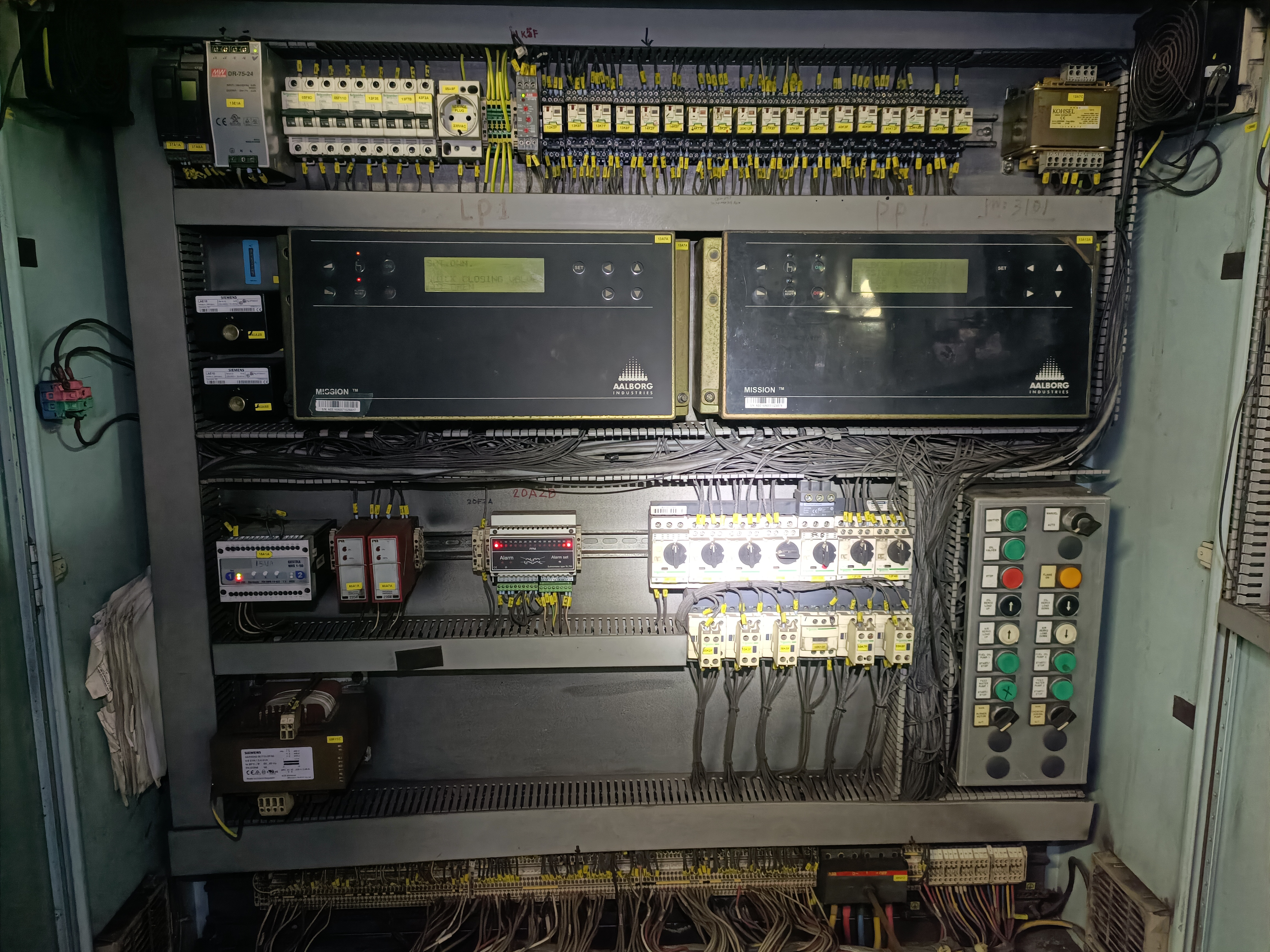
Aboard a vessel docked at Dalian Oil Terminal, the Aalborg boiler suffered an unexpected fault and could not be operated remotely. The crew could only run the equipment locally to maintain port discharging and deck machinery operation on a temporary basis. Failure to rectify the fault promptly would disrupt the vessel’s discharging schedule and departure arrangement, pose risks to vessel and personnel safety, and cause substantial economic losses to the shipowner.
Upon receiving the emergency service request, our professional technicians rushed to Dalian Oil Terminal without delay to troubleshoot and resolve the issue, striving to minimize operational risks and financial losses for the vessel.
After boarding the ship, our technicians communicated with the ship’s crew to clarify the fault details, inspected the on-site equipment and reviewed relevant technical documents. Following the working principle of checking hardware before systems and local circuits before remote circuits, we launched the troubleshooting work as detailed below:
Part I. Fault Description
1.1 When the boiler was started in remote mode, the LP1 controller continuously displayed VALVE CLOSING, and the equipment activated boiler shutdown protection, failing to operate remotely.
1.2 In local manual mode, the boiler started, stopped and burned normally.
1.3 Supplementary Note: This alarm is a standard flame failure protection function of Aalborg MISSION series boilers. In compliance with SOLAS safety regulations, the controller will cut off the fuel supply immediately if no valid flame is detected within the ignition sequence, so as to prevent oil accumulation inside the furnace and avoid explosion hazards.
Part II. Comprehensive Hardware Inspection
2.1 Inspection of LP1 Main Controller
2.1.1 Check power supply and indicator lights
2.1.1(1)The DC24V power supply was stable and the power indicator on the panel stayed on.
2.1.1(2)Operating, fault and flame indicator lights were checked, confirming the controller ran normally.
2.1.2 Output circuit test
2.1.2.1 Switched to manual mode and tested the circuits of fans, fuel pumps and ignition transformers in sequence. All corresponding contactors operated properly.
2.1.3 Inspection Conclusion The LP1 controller delivered normal output, and the rear contactors worked in good condition.
2.2 Inspection of Flame Amplifier and UV Sensor
2.2.1 LED indicator check
The flame indicator dimmed, which was initially judged to be caused by contamination or circuit abnormality of the UV sensor.
2.2.2 Troubleshooting measures
2.2.2(1)Cleaned the UV sensor installed inside the furnace, and the flame signal returned to normal.
2.2.2(2)Measured the output signal with a multimeter, verifying that the module could steadily transmit flame presence/absence signals to the LP1 controller.
2.2.3 Inspection Conclusion The flame amplifier and UV sensor functioned normally with stable signal transmission.
2.3 Inspection of Ignition Transformer, Contactors and Circuit Breakers
2.3.1 Ignition transformer inspection
2.3.1(1)The indicator light worked normally, and no burning odor was found on the unit.
2.3.1(2)The high-voltage cables were intact with no insulation damage or electric leakage.
2.3.1(3)Normal high-voltage discharge sound was heard during ignition, eliminating faults of the equipment itself and connecting circuits.
2.3.2 Contactor and circuit breaker inspection
2.3.2(1)No burning or discoloration was found on contactor contacts.
2.3.2(2)Circuit breakers did not trip and could close reliably after reset.
2.3.2(3)The coil supply voltage was measured and confirmed normal.
2.3.3 Inspection Conclusion
The ignition transformer, contactors and circuit breakers were all in sound condition with no hardware defects.
Overall Hardware Conclusion
All hardware components of the boiler, including the LP1 controller, flame amplifier, UV sensor, ignition transformer and power actuators, operated normally.
Supplementary Analysis: Local control and remote control adopt two independent circuits. In local mode, the control cabinet automatically bridges remote interlock contacts to authorize ignition and fuel valve operation, hence normal local operation. In remote mode, the equipment relies on interlock permission signals sent by the external AMS. Therefore, the fault was locked within remote signal circuits, interlock loops and mode switching circuits.
Part III.Troubleshooting of Remote Interlock and Circuits
3.1 Fault Analysis
After remote startup, the LP1 controller triggered the alarm Remote interlock missing.
Fault Logic: The LP1 controller received the remote start command normally, but failed to obtain the interlock signals for ignition and fuel valve opening. The ignition sequence was interrupted, resulting in the fuel valve opening while the ignition system stayed inactive. No flame was formed inside the furnace, and the UV sensor sent a no-flame signal to the controller. The LP1 then activated flame failure protection and closed the fuel valve, displaying VALVE CLOSING on the screen.
Considering the on-site operating conditions, the fault was likely caused by loose terminals, defective transfer relays or open circuits on the connecting lines between AMS and LP1.
3.2 Measurement of Hardwired Signals (Tested under Remote Mode)
3.2.1 Tools Preparation
3.2.1(1)Tools: Digital multimeter, flashlight, insulating gloves.
3.2.1(2)Gear setting: DCV gear for DC24V voltage measurement; continuity/buzzer gear for passive dry contact test.
3.2.1(3)Keep the control cabinet in Remote mode during the whole test.
3.2.2 Remote start command measurement
3.2.2(1) Locate the terminals marked Remote Start / Remote Run on the LP1 terminal block.
3.2.2(2)Request the crew to keep sending remote start commands via the engine room control station / AMS.
3.2.2(3)Test the voltage of corresponding terminals with a multimeter.
3.2.2(4)Test Result: A stable DC24V voltage was detected, indicating the remote start command circuit worked properly.
3.2.3 Measurement of Start Permit / Run Permit (Passive Dry Contact)
3.2.3(1)Switch the multimeter to continuity gear and connect probes to the interlock terminals.
3.2.3(2) Maintain remote mode and continuous remote start command.
3.2.3(3) Test Result: The contact remained open with no buzzer sound.
Fault Explanation: The LP1 received the start command but failed to obtain the safety permission for ignition and fuel supply. The program was suspended, and no ignition occurred after fuel injection, which eventually triggered boiler shutdown protection.
3.3 Fault Location by Temporary Jumper Test
Connected the two terminals of the start permit circuit with a short wire for temporary bridging.
Safety Warning: The temporary jumper was only used for fault diagnosis, which bypassed safety interlocks. The test was conducted under full supervision, and the jumper must be removed immediately after testing. Permanent bridging of safety protection circuits is strictly prohibited.
After sending the remote start command again, the boiler ignited and operated normally, and the VALVE CLOSING alarm disappeared.
Conclusion: The fault existed in the AMS system, or in the connecting lines and transfer relay circuits between AMS and the boiler control cabinet.
3.4 Segmented Inspection and Maintenance
3.4.1 AMS System Inspection
Checked the corresponding output points in the AMS system. All points were activated normally with no parameter shielding, system locking or associated alarms, proving the AMS itself worked well.
3.4.2 Engine Room Transfer Relay Inspection Signals output from AMS were transmitted to LP1 via transfer relays.
After inspection, the relay coil was energized and the indicator light was on. Disassembly inspection confirmed poor contact of the relay main contact, which was the root cause of the fault.
3.4.3 Supplementary Analysis The engine room is always subject to severe conditions including intensive vibration, high humidity and oil-gas dust. Such environment easily leads to oxidation and increased contact resistance of relay contacts, resulting in latent faults where coils are energized but contacts cannot close reliably. This is a common fault of marine electrical equipment.
3.4.4 Maintenance Work
Replaced the faulty relay with a new one of the same model. The boiler resumed normal remote operation after repeated tests. Removed the temporary jumper and restored all original connections.
Part IV. Overall System Re-test
All wiring and original settings were restored. Multiple mode switching and startup/shutdown tests were carried out. The boiler operated with normal logic and no alarms or abnormal protection actions. The fault was completely eliminated, and the emergency repair work was successfully completed.
Part V . Fault Summary & Maintenance Recommendations
5.1 Root Cause
Poor contact of the transfer relay in the remote interlock circuit cut off the start permit signal to LP1. The abnormal ignition sequence triggered flame failure protection and the VALVE CLOSING alarm.
5.2 Prediction of Similar Faults
Vibration, humidity and dust in the engine room tend to cause poor contact of relays, wiring terminals and mode switches. If the alarm Remote interlock missing appears again, priority shall be given to inspecting transfer relays, line terminals and AMS output points.
5.3 Daily Maintenance Suggestions
5.3.1 Regularly fasten all terminals of remote control circuits and remove oil contamination and dust on relay surfaces.
5.3.2Arrange periodic inspection and rotational replacement for long-running transfer relays to prevent failures caused by component aging.
5.3.3Pay attention to interlock status prompts on LP1 when switching between local and remote modes, so as to detect and eliminate hidden troubles at an early stage.
Part VI. Write at the end:
The upgrading and popularization of new technologies and equipment represent the inevitable trend of industrial development and labor optimization. Even the most advanced equipment operates in accordance with fixed rules and maintenance requirements. The wide application of intelligent devices and automatic systems in the marine industry has injected strong vitality into the whole sector.
Temporary unfamiliarity with new technologies is exactly an opportunity for us to learn steadily, accumulate experience and improve professional competence. Mastering new equipment proficiently helps guarantee safe navigation of vessels and upgrade our technical capabilities. We will keep a lifelong learning attitude and provide reliable professional technical support for the stable operation of various marine equipment.



 +8615005328513 (wechat ) +8613606393913 (Whatsapp)

 No. 8888, Huangshan Road, Huangdao District, Qingdao City, Shandong Province, China.