All our technical services are centered on safeguarding the safe navigation of vessels; delivering efficient and reliable on-site maintenance has always been our service tenet.
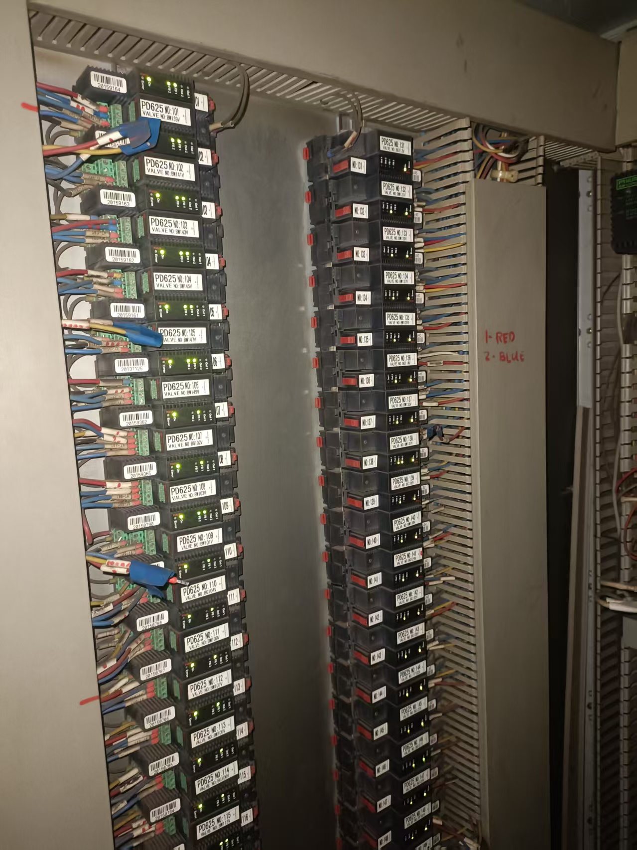
A long-term shipowner entrusted us to conduct special maintenance on the ballast water control system of a large bulk carrier docked at Zhoushan Shipyard. Multiple electrical faults existed in the vessel’s PLC remote-controlled hydraulic valve groups, which severely disrupted regular ballast loading and discharging operations. The faults not only delayed the vessel’s loading and unloading schedule, but also created major potential risks to hull structural safety.
Customer demands equal operational orders. Our project team immediately dispatched senior service engineers to board the vessel for on-site troubleshooting and maintenance.
Part I: On-site Fault Investigation & Pre-inspection of Control Cabinet
1..1 Summary of Fault Phenomena
After boarding the vessel, service engineers communicated with the chief engineer to conduct a full inspection of the system. All identified faults are summarized as follows:
(1) The On power indicator of some PD625 modules was completely off with no operational lights lit, rendering the corresponding hydraulic valves fully non-functional for remote control.
(2) The PLC output terminals had sent out 24V control signals, yet the Out1 and Out2 output indicators of the modules failed to light up. Remote ballast loading and discharging operations could not be performed in the engine control room.
(3) After the PLC sent valve open/close commands, neither the FB1 nor FB2 valve position feedback indicators lit up. The central control system could not determine the actual valve position, triggering interlock protection that locked the system and prevented generators and ballast pumps from starting.
(4) The FB1 and FB2 feedback indicators of certain PD625 modules stayed illuminated simultaneously, causing conflicting valve position signals and frequent false fault alarms in the central control system.
(5) The Error red fault light of modules remained on constantly, locking the corresponding output channels. The hydraulic valves could only operate in one direction, with reverse control functions disabled.
1.2 Pre-inspection Work on Control Cabinet
Upon arriving at the electrical control cabinet, service engineers carried out preliminary inspections following standardized procedures:
(1) Locate all faulty PD625 modules one by one and cross-verify the corresponding faults for each unit. Simultaneously check the tightness of internal cabinet terminals and identify visible hazards including corroded wiring, burnt insulation and aging cables.
(2) Retrieve the original technical drawings of the vessel’s ballast electrical control system, check the PLC monitoring screen in the engine control room, and fully record real-time valve position data as well as historical system alarm logs.
(3) Adhere strictly to the troubleshooting principle: near first, far later; electrical faults first, mechanical faults later. Prioritize inspection of electrical circuits inside the control cabinet. Only after confirming intact wiring and modules shall engineers go on deck to inspect hydraulic valve actuators, limit switches and other mechanical components.
Part II: Detailed Troubleshooting & Maintenance Procedures for Classified Faults
2.1 Fault Phenomenon
The On power indicator of PD625 modules is completely off with no operational lights lit, rendering the corresponding hydraulic valves fully non-functional for remote control.
2.1.1 Maintenance Process
(1) Safe Power Cut-off Operation:
Disconnect the air switch of the electrical branch circuit to which the faulty module belongs. Strictly perform voltage verification to eliminate risks of short circuit and electric shock during live maintenance.
(2) Inspection of Front-end Power Supply Circuit:
PD625 modules operate on DC24V power supply. Each row of modules is equipped with independent air switches and fuses for overload protection.
① Measure the voltage at the output terminals of branch fuses and air switches with a multimeter; DC24V power supply was measured normal.
② No air switch tripping or blown fuses were found, eliminating the need for component replacement or resetting.
③ Fully inspect the main power supply cables of the modules. Cable sheaths were intact with no corrosion or insulation breakdown to ground; the entire power supply circuit was fault-free.
(3) Maintenance of Wiring Terminals:
Disassemble the power terminals at the rear of the modules. Clean oxidized, rusted and greasy terminal surfaces, then retighten all power cables to ensure firm crimping and reliable electrical contact. All operations were implemented in full compliance with technical specifications.
(4) Replacement Test of Module Body
① All front-end power supply, wiring and terminals were inspected with no abnormalities, confirming the fault was confined to the module itself.
② Replace the faulty unit with a spare intact PD625 module for testing. The module On power indicator lit up normally after power-on.
③ Diagnosis: The internal power circuit of the original faulty module was burnt out. The shipowner is advised to send the module for factory repair or purchase a brand-new replacement.
2.2 Fault Phenomenon
The PLC output terminals have sent out 24V control signals, yet the Out1 and Out2 output indicators of the modules fail to light up. Remote ballast loading and discharging operations cannot be performed in the engine control room.
2.2.1 Maintenance Process
(1) Safe Power Cut-off Operation:
Notify the on-duty engineer in the engine room to lock ballast system operations and hang maintenance warning signs. Disconnect the independent 24V air switch for ballast valve PLC output circuits inside the control cabinet. Recheck the voltage of PD625 signal input terminals with a multimeter until the reading returns to 0V. Only after confirming complete power cut-off of the control circuit may engineers disassemble wiring for maintenance.
(2) Inspection of Control Signal Circuits:
Engineers send valve operation commands from the engine control room, then measure voltage at both PLC output terminals and PD625 signal input terminals with a multimeter set to DC voltage range. Stable DC24V readings were obtained at both points, together with lit indicator lights on the PLC panel, verifying that the PLC side successfully issued control signals.
① Recheck the voltage between PLC output terminals and PD625 input terminals to confirm stable delivery of DC24V control commands.
② Disassemble the green signal terminal blocks of the modules, clean oxidized and rusted debris on terminal surfaces, and re-crimp loose and frayed control cables to guarantee stable conductivity.
(3) Simulation Test via Channel Switching:
Transfer the PLC control output cables to the spare input channel of the module, then send open/close valve commands remotely to observe the status of output indicators. Out1 and Out2 still showed no lighting after cable switching, ruling out faults in external wiring.
(4) Fault Diagnosis & Disposal
① No abnormalities found in external signal circuits and terminals, confirming damage to the internal signal receiving circuit of the module.
② Install a spare PD625 module for power-on testing. The Out indicators light up synchronously with control commands, restoring remote ballast loading and discharging functions.
③ Advise the shipowner to purchase a brand-new replacement module.
2.3 Fault Phenomenon
After the PLC sends valve open/close commands, neither the FB1 nor FB2 valve position feedback indicators light up. The central control system cannot confirm actual valve position, triggering interlock protection and preventing generators and ballast pumps from starting.
2.3.1 Maintenance Process
(1) Segregate Feedback Circuits:
Disconnect the external FB feedback harness running from PD625 modules to deck hydraulic valves, then use short-circuit wires to directly bridge the FB1 and FB2 terminals of the module for simulated signal testing.
(2) Fault Zone Classification & Corresponding Disposal
① If FB1 and FB2 indicators light up normally after terminal bridging, the fault lies within feedback circuits on the valve side: Go on deck to disassemble hydraulic valve limit boxes, clean rust and oxide deposits on limit switch contacts, measure continuity of feedback cables section by section, and replace deck feedback cables with broken cores or damaged insulation. For this maintenance case, valve-side wiring repairs fully restored valve position feedback signals.
② If feedback indicators remain unlit after terminal bridging, the internal feedback acquisition channel of the module is damaged and a spare PD625 module must be replaced.
(3) Interlock System Reset: Upon completion of feedback circuit maintenance, proceed to the engine control room to lift system interlock locks. Recheck by sending remote operation commands; both generators and ballast pumps can start normally.
(4) Maintenance Suggestions: In response to the cable damage encountered during this repair, establish a regular inspection schedule for deck cables and stock spare cables of matching specifications in advance to avoid recurring similar faults.
2.4 Fault Phenomenon
The FB1 and FB2 feedback indicators of some PD625 modules stay illuminated simultaneously, causing conflicting valve position signals and frequent false fault alarms in the central control system.
2.4.1 Maintenance Process
(1) Distinguish Debug Jumpers from Hardware Faults:
Cut off power and disassemble terminal blocks of faulty modules to check for residual cross-connect jumpers left from system debugging. No external test jumpers were found in this case, eliminating manual debugging factors and confirming a hardware wiring fault.
(2) Inspection of Valve-side Wiring:
Disconnect external FB feedback harnesses on the valve side and restore power to observe indicator status. FB1 and FB2 indicators went out synchronously after disconnection, confirming the root cause was short-circuited FB1 and FB2 cables corroded and stuck together inside the valve limit box.
Key Technical Explanations
1. Reason for simultaneous shutdown of FB1 & FB2 after disconnecting valve-side harnesses:
The short-circuit point between the two feedback lines is located in wiring from the valve box to deck cables. Disconnecting the harness fully cuts off the conductive path between modules and valves, breaking the feedback current loop and turning off both indicators, thereby pinpointing the fault location.
2. Two sets of judgment logic for fault classification:
① Disconnect valve harnesses → FB1 & FB2 turn off: Short-circuit occurs at valve or deck cable side
② Disconnect valve harnesses → FB1 & FB2 remain lit: Short-circuit exists in internal module acquisition circuits, indicating hardware damage to the PD625 unit.
3. Principle of Simultaneous Illumination of Dual Feedback Indicators:
FB1 and FB2 are two completely independent feedback signal lines. Corroded and broken insulation makes internal copper cores adhere together, permanently connecting the two circuits — an effect identical to manually bridging FB1 and FB2 terminals with jumpers. The circuit conduction is no longer controlled by valve limit switches, keeping both feedback loops energized continuously and lighting FB1 and FB2 at all times.
4. Repair Procedures for Valve-side Faults
① Disassemble hydraulic valve limit boxes, separate bonded feedback cables and re-insulate damaged wire cores;
② Replace aging limit travel switches with hidden rust risks.
(3) Alternative Disposal for Module-side Faults:
If both feedback indicators stay lit after disconnecting valve harnesses, the internal feedback acquisition circuit of the module has broken down, requiring replacement of a brand-new PD625 spare unit.
(4) System Alarm Clearing & Function Verification:
Restart the electrical control system after wiring repairs, clear all historical valve position conflict alarms on the PLC monitoring interface, and operate valves remotely multiple times. The valve position display remains stable with no frequent false alarms generated.
2.5 Fault Phenomenon
The Error red fault light of modules stays illuminated constantly, locking the corresponding output channels. The hydraulic valves can only operate in one direction, with reverse control functions disabled.
2.5.1 Maintenance Process
(1) Load Isolation Test:
Operation Steps: Cut off power and unplug the red & blue drive cables connecting the Out ports of modules to solenoid valves, then restore power to observe the Error fault light. The red light turned off after cable disconnection in this case, confirming the fault was located at solenoid valves and external drive wiring.
Principle Explanation: Solenoid valve coils and matched drive cables act as the output-side load of PD625 modules. Disconnecting drive cables at Out ports isolates external loads to distinguish fault locations:
① If the Error red light goes out after power-on with cables disconnected: Short-circuit or overload faults exist in solenoid valve coils or external drive cables;
② If the Error red light stays lit after power-on with cables disconnected: Internal output drive power tubes of the module are burnt out, representing hardware damage to the module body.
(2) Maintenance of Solenoid Valves & Cables:
① Measure resistance of two groups of solenoid valve coils with a multimeter. Replace the complete hydraulic solenoid valve if coils show short circuit or open circuit;
② Inspect deck drive cables section by section, and perform insulation repair or cable replacement at positions with broken insulation or seawater-induced corrosion breaks.
(3) Alternative Disposal for Module Faults:
If the Error red light remains on after disconnecting external valve cables, single-channel drive power tubes inside the module are burnt out and a brand-new PD625 module must be replaced.
(4) Bidirectional Function Verification:
After completing all maintenance work, send alternating open/close valve commands remotely from the engine control room for repeated testing. The hydraulic valve operates smoothly in both directions, the Error red fault light stays fully off, and no system alarms appear, marking full fault recovery.
Part III : Reference for Other Common Derivative Faults of Ballast Valve Control System
3.1 Intermittent Indicator Flickering & Unstable Operation
① Loose terminals or half-broken wire cores caused by vessel vibration;
② Poor internal welding of solenoid valve coils leading to unstable conduction under vibration;
③ Oxidized contacts of limit switches resulting in inconsistent contact performance.
3.2 PD663 Expansion Module Power Indicator Off
Fault Impact: Loss of power prevents all valve position signals from uploading to the PLC.
Troubleshooting: Inspect power supply fuses and series wiring terminals. Replace the PD663 module if the power indicator remains off with normal power input.
3.3 On-site Troubleshooting Mnemonics
① No On light → Check power supply & fuse
② Red Error light → Test valve coil & output wiring
③ Out lit but no FB → Inspect mechanical jamming & limit switch
④ Both FB1 & FB2 on → Check test jumpers or shorted feedback cables
⑤ Intermittent flashing → Retighten all loose terminal wiring
Part IV: Write at the end
We have always believed that the best equipment is not defined by cutting-edge technology or premium configurations.
Only equipment with regular standardized maintenance, stable and reliable performance under critical conditions, and trustworthy operation can be deemed truly high-quality equipment. It is an undeniable reality that all mechanical equipment is susceptible to faults. Routine maintenance is therefore a fundamental prerequisite for stable long-term equipment operation, with both on-board upkeep and shore-based overhaul being indispensable.
Moreover, hidden equipment faults can only be identified and properly resolved by professionals familiar with equipment principles and proficient in practical operation. Ultimately, equipment will only serve those who can master and take good care of it.
The sea is the strictest examiner, and time the most impartial judge. For all vessels braving wind and waves to fulfill shipping missions, how to guarantee safe return from every voyage is a long-term research topic for us. Only through continuous learning and accumulation of on-site practical experience, as well as proficient command of operation and management for all on-board equipment, can we withstand the harsh tests of marine environments, slow equipment aging and wear, and hold the bottom line of vessel navigation safety.



 +8615005328513 (wechat ) +8613606393913 (Whatsapp)

 No. 8888, Huangshan Road, Huangdao District, Qingdao City, Shandong Province, China.