The ship’s ballast water automation system directly determines the efficiency of hull stability control. Featuring high integration and continuous high-frequency operation, it serves as a core operation and maintenance module of ship automation. Entrusted by a long-term shipowner client, our company dispatched engineers to Dalian Shipyard to conduct special fault maintenance for the ballast system of a docked bulk carrier.
Onboard fault feedback: The level readings of multiple ballast tanks exhibited continuous drift with distorted collected data, causing the system to frequently issue incorrect valve switching commands. The repeated unnecessary start-stop of ballast pumps and marine auxiliary generator accelerated electromechanical equipment wear and increased crew duty workload. If left unrectified, inaccurate ballast adjustment will disrupt loading and unloading operations at ports, resulting in substantial ship demurrage charges and operational losses. To minimize client losses, our engineers boarded the vessel immediately with a full set of professional calibration tools to complete troubleshooting and maintenance within a time limit.
Part I Onboard Fault Collection and Maintenance Plan Formulation
1.1 On-site Fault Verification
After boarding the vessel and communicating with the duty engineer, the core fault phenomenon was confirmed: the level values of multiple ballast tanks drifted slowly and continuously without stable and valid output data. This prevented accurate control of ballasting and deballasting processes, increased crew operational & working pressure, and caused long-term excessive wear of marine electromechanical equipment.
1.2 Adverse Effects of the Fault
First, distorted level data fails to support precise ballasting and deballasting operations, leaving hull trim and stability adjustment without reliable data reference.
Second, the fault covers multiple dimensions including signal acquisition, circuit transmission, valve control and PLC logic, featuring concealed fault points and a wide troubleshooting range, which tends to prolong maintenance cycles and affect ship operational schedules.
1.3 System Principle Analysis (Foundation for Rapid Fault Location)
The troubleshooting was carried out based on the closed-loop logic of the ballast automation system:
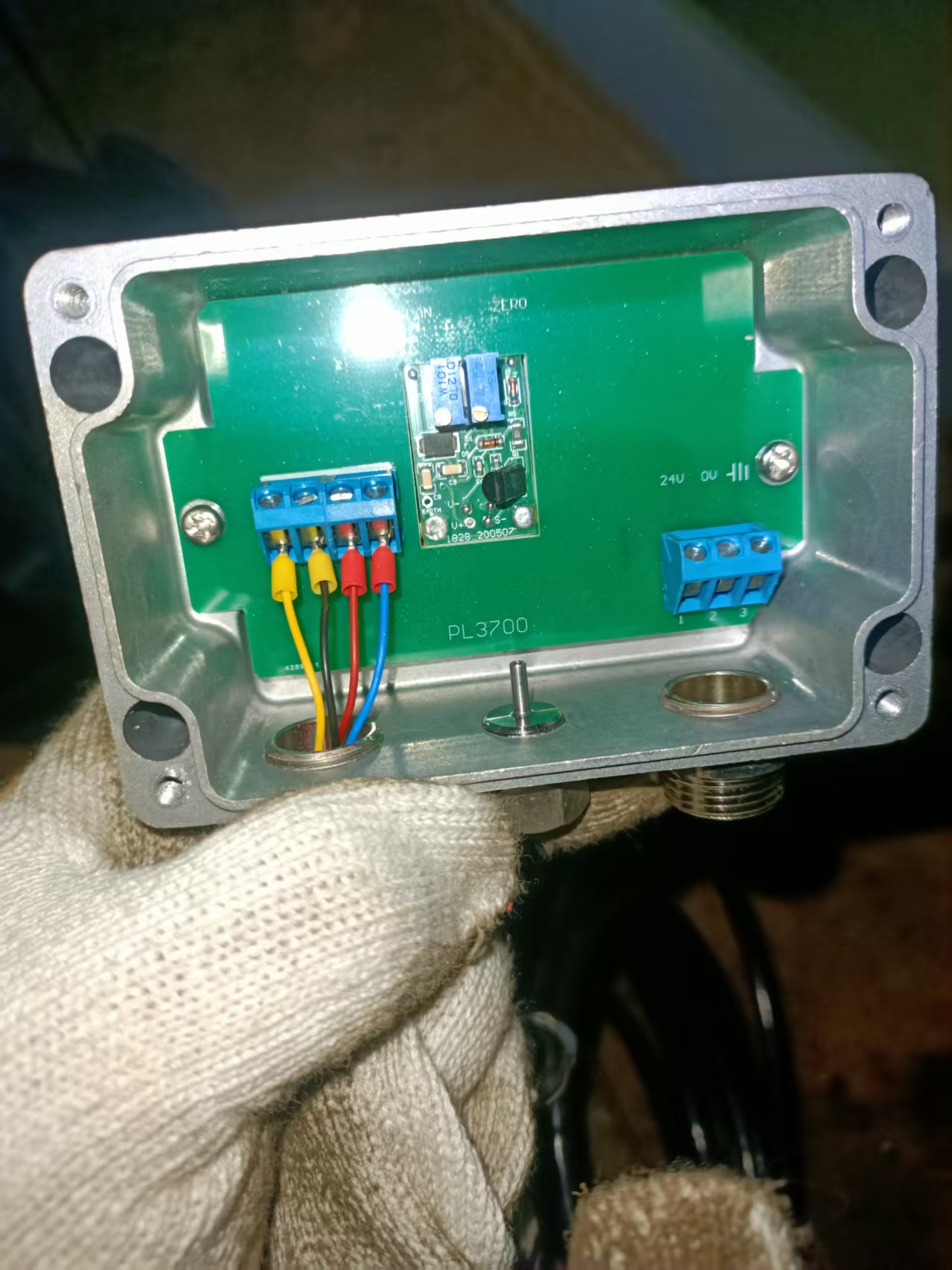
Hydrostatic probe level acquisition → PL3700 transmitter 4-20mA analog signal conversion → PLC logical operation in engine control room main control system → PD625 valve control module actuates hydraulic valve → valve position FB1/FB2 feedback signals return to PLC.
1.4 Segmented Isolation Troubleshooting Scheme
Combined with fault phenomena and practical marine operation experience, the faults were preliminarily confined to the front-end hydrostatic probe and PL3700 level transmitter acquisition links.
To avoid blind disassembly and inefficient troubleshooting, a backward progressive isolation method starting from the PLC system to front-end sensors was adopted to narrow down the fault scope and accurately identify faults in PLC channels, transmission cables, valve control modules or transmitter acquisition units.
Part II On-site Segmented Isolation Troubleshooting Implementation
Core troubleshooting logic: The PD625 valve control module is only responsible for valve actuation and position feedback without participating in level signal acquisition, so it can be preferentially isolated and excluded to lock faults in the front-end signal acquisition link.
1. PD625 Valve Control Module Isolation Test:
(1)Disconnect the output control cables of the PD625 module for the faulty tank at the engine room control cabinet,
(2)Mechanically lock the deck hydraulic valves, and disable the automatic valve control logic of the system.
(3)Then let the system stand for 10 minutes for observation.
(4)Observation result: The level readings on the PLC display screen still drift continuously.
(5)It can completely rule out faults in the PD625 module, hydraulic valves and valve position feedback loops, and the continuous drift is not caused by pipeline pressure fluctuations.
2. PLC Analog Input Channel Verification:
(1)Disconnect the 4-20mA signal line from the PL3700 transmitter to the PLC, Connect a standard signal generator to the analog input channel, and output a constant 12mA current (standard current for 50% medium liquid level).
(2)Observation result: The level reading on the engine room monitoring screen remained stable without drift, proving that the PLC mainboard and IO acquisition channels functioned normally, and the fault did not exist in the engine room main control system.
(3)Disconnect the red and blue signal cables of the tank bottom hydrostatic probe from the input terminals of the PL3700 transmitter, while retaining the 24V working power supply for the transmitter.
(4)Connect a multimeter in series to the 4–20mA output loop to monitor the stability of the 4mA zero-point current under no-load conditions.
(5)Test result: Under zero-pressure no-load state, the transmitter output current fluctuated continuously with slow zero-point offset, directly confirming that the fault originated from the PL3700 transmitter itself.
3. Cross-Verification Troubleshooting of Hydrostatic Probe and Deck Transmission Cables
(1) Cable Insulation Detection:
Open the junction box of the tank bottom hydrostatic probe, disconnect the probe from the deck long-distance cable, and test the cable insulation resistance to ground with a megohmmeter.
Found the insulation resistance was ≥1MΩ, indicating no cable damage or seawater ingress, and eliminating signal abnormality caused by cable leakage.
(2) Independent calibration of hydrostatic probe:
Apply constant rated pressure to the hydrostatic probe via a standard pressure calibrator and monitor its output signal throughout the test.
Found The reading remains stable without any offset, verifying that the probe diaphragm is intact with no corrosion, leakage or jamming faults.
Part III Fault Root Cause Confirmation and Equipment Principle Review
After full-link segmented isolation and cross-verification, the root cause of the continuous level drift fault is the failure of the PL3700 marine level/pressure transmitter itself. As the core front-end acquisition unit for ballast tank liquid level, the PL3700 operates independently of the PLC system with the following core functions:
1. The input terminal connects with the tank bottom hydrostatic probe to accurately collect seawater hydrostatic pressure inside the tank and convert it into corresponding liquid level height;
2. The signal standard definition: 4mA corresponds to the empty tank zero-point state, and 20mA corresponds to the full tank range state, with the current value linearly corresponding to the real-time liquid level.
Combined with previous troubleshooting results and original equipment technical data, the root causes of the level drift fault are confirmed as aging of the ZERO potentiometer and oxidized loose connection of wiring terminals.
Part IV Standard on-site maintenance procedures are as follows:
4.1 Disconnect the PD625 valve control output cable of the corresponding tank, mechanically lock the deck hydraulic valve, and turn off the automatic adjustment program of the ballast system to completely avoid accidental valve start-stop risks during maintenance.
4.2 Open the transmitter housing, clean condensation on the circuit board, and finely polish the metal contacts of the ZERO potentiometer to remove surface oxidation layers and restore potentiometer adjustment accuracy.
4.3 Polish the oxidized and corroded parts of the transmitter input and output terminal copper sheets, retighten all wiring screws, and apply anti-rust grease evenly on terminal contact surfaces to eliminate signal drift caused by loose and oxidized connections.
4.4 To eliminate potentiometer coupling interference, strictly perform dual-point cyclic calibration of no-load zero point and full-load range. The detailed operation steps are as follows:
(1) No-load Zero Calibration: Keep the transmitter powered by 24V normal voltage, disconnect the signal cable of the hydrostatic probe, and place the device in a pressure-free no-load state.
Slightly adjust the ZERO potentiometer with a flat-head screwdriver, monitor the output current in real time via a multimeter, and fine-tune until the current stabilizes at 4.00mA without locking the potentiometer temporarily.
(2) Full-load Range Calibration: Connect a standard pressure calibrator to the pressure acquisition interface of the transmitter, boost pressure slowly to the rated full-load static pressure of the tank, and adjust the SPAN potentiometer steadily to calibrate the output current accurately to 20.00mA.
(3) First Zero Recalibration: Slowly release the pressure of the calibrator to restore the no-load state. If the current value deviates from 4.00mA, only fine-tune the ZERO potentiometer for correction while keeping the SPAN potentiometer unchanged.
(4) First Range Recalibration: Repressurize to the rated full-load pressure, verify the standard 20mA current, and only fine-tune the SPAN potentiometer if deviation occurs.
(5) Secondary Cyclic Error Elimination: Repeat the complete zero and range calibration process for secondary recheck. Ensure the current stably maintains 4.00mA at no-load state and 20.00mA at full-load state with linear and offset-free current output under medium pressure, so as to completely eliminate coupling errors.
4.5 Front-end Cable Recheck and Restoration
Clean corrosion on the wiring terminals of the tank bottom hydrostatic probe, recheck the cable insulation resistance to ground with a megohmmeter (ensuring the value ≥1MΩ), and restore all wiring connections.
4.6 Complete Machine Joint Debugging and Acceptance
Restore all system circuits, compare the monitor data with actual liquid level measured by manual sounding ruler, and observe continuously for 30 minutes. Stable level readings without drift and within standard error range confirm qualified maintenance.
Part V Summary of Common Faults, Troubleshooting and Maintenance for PL3700 Transmitter
Fault 1: Fixed Stuck Level Reading
Causes: Broken probe signal cable, damaged calibration small-board chip
Maintenance Steps:
1. Reconnect broken cables or replace new signal cables;
2. Replace the transmitter calibration unit or the entire PL3700 transmitter if the calibration board chip is damaged;
3. Perform standard zero and range calibration after wiring restoration to ensure level readings change normally with pressure.
Fault 2: No Liquid Level Signal Output
Causes: Loose 24V power terminal, burnt internal power supply circuit
Maintenance Steps:
1. Fasten power terminals and polish oxidized contact surfaces;
2. Repair damaged power circuits and replace faulty insurance components;
3. Replace the PL3700 transmitter unit if the internal power circuit is burnt out, and verify normal signal output after power-on.
Fault 3: Large Deviation in Medium Liquid Level (Normal zero and full range, excessive medium-segment error)
Causes: Single-point non-cyclic calibration, linear distortion caused by potentiometer coupling interference
Maintenance Steps:
1. Perform standard dual-point calibration: adjust ZERO to 4mA under no-load condition and SPAN to 20mA under full pressure;
2. Eliminate coupling deviation through two cyclic recalibrations;
3. Complete calibration when manual sounding comparison confirms qualified medium-level accuracy.
Part VI Write at the end
Ship automation systems feature high integration and complex equipment links. Superficial simple faults often involve multi-dimensional linkage problems of electrical, mechanical and automatic equipment. In complex system structures, sorting out control links rapidly and isolating fault points accurately are the most basic and core capabilities of marine equipment maintenance.
No matter how complex an automation system is, it operates based on fixed hardware structures and control logic, and all equipment faults are traceable. Only by penetrating superficial phenomena to explore essential causes and conducting scientific troubleshooting based on system principles can blind maintenance be avoided and fault handling efficiency improved.
There are no shortcuts in equipment operation and maintenance. Accurate on-site fault judgment and efficient maintenance processing all derive from daily accumulation and in-depth mastery of equipment principles, structures and maintenance specifications. Refined daily maintenance and technical accumulation provide solid confidence for handling sudden faults.
Marine equipment operates strictly in accordance with inherent mechanical and program logic. Equipment abnormalities are never accidental, but feedback of hardware aging, insufficient maintenance and parameter deviation. In the face of faults, we should avoid fluke mentality and evasion, and adopt professional knowledge and standard procedures for disposal.
Adhering to standardized maintenance, accurate troubleshooting and scientific debugging can effectively reduce the failure rate of ship automation equipment, ensure stable operation of ballast systems, cut down ship operational losses, and guarantee safe and efficient navigation of vessels.



 +8615005328513 (wechat ) +8613606393913 (Whatsapp)

 No. 8888, Huangshan Road, Huangdao District, Qingdao City, Shandong Province, China.