With the continuous upgrading of marine automation, the daily equipment management capability of engineers has also improved. Simple single-point equipment faults can mostly be repaired on board by the ship’s crew. However, system-wide and full-range complex faults often leave shore-based automation maintenance teams with highly challenging inspection and repair tasks.
This case involves a fault in the engine room automation system of a bulk carrier docked at a shipyard in Yantai. The fault was not caused by damage to a single peripheral device such as a transmitter or valve module; instead, the entire IO control subsystem suffered universal communication disorder and functional breakdown, requiring professional shore-based automation engineers to attend the vessel for troubleshooting. Having been deeply engaged in marine electrical automation services for many years, we have accumulated a large number of similar system troubleshooting and maintenance cases, and possess mature capabilities in hardware detection and system joint commissioning. This is the core reason why ship owners and engineering teams entrust us with complex fault repairs
Entrusted and trusted by the ship owner, our company immediately dispatched automation engineers with a full set of testing tools to board the vessel for maintenance. After docking and communicating with the chief engineer, we sorted out the complete set of fault phenomena as follows:
Part 1 Summary of Fault Conditions
1. Universal Failure of Peripheral Devices in Ballast Tank Automation System
(1) The measured values of liquid level transmitters across all tanks fluctuate irregularly;
(2) Ballast valve control modules cannot receive opening/closing commands issued by the main board, and multiple independent front-end peripheral devices malfunction simultaneously.
2. Complete Communication Interruption of Engine Room Monitoring System
(1) On the upper monitoring screen, all measuring points managed by this IO main board are offline without any fault alarm push.
(2) Multiple re-pluggings of terminal wiring and retests with brand-new transmitters/valve modules failed to eliminate the fault.
3. Intermittent Complete System Malfunction
(1) Under vessel vibration during navigation and high-temperature operating conditions in the engine room, a batch of monitoring points lose communication.
(2) After powering off and cooling down for a period, the system can resume normal operation temporarily
(3) Once powered on again, with the fault recurring periodically.
4. Preliminary Analysis of Root Cause
(1)All analog and digital signals collected by sensing and execution equipment in the engine room, including liquid level transmitters, valve execution modules and generator ECU units, are ultimately aggregated to the IO main control board for logical operation and control command issuance. This main board serves as the core data hub of the engine room automation subsystem.
(2)During sea voyages, frequent triggers of monitoring failure and interlock misoperation include aging main board hardware, oxidized loose terminals, depleted backup lithium batteries and damaged core chips.
(3)If only a single transmitter fails, merely the corresponding single measuring point will malfunction. The simultaneous failure of multiple peripheral devices in this case confirms that the root cause lies in hardware damage of the IO main control board as a whole.
5. General Troubleshooting Logic
Plan to conduct layered verification following the principle of peripheral inspection first, core inspection second; simple checks first, complex checks second:
(1) Verify the 24V power supply of the main board and the tightness of wiring terminals, and conduct single-loop tests on peripheral equipment to rule out faults of cables, transmitters and valve modules themselves.
(2) After confirming the fault resides inside the main board, further locate whether the damaged component is the main control CPU chip, or peripheral components including flash memory, crystal oscillator, resistors, capacitors and switches.
Part 2 Step-by-Step On-site Troubleshooting Procedures
Pre-operation Safety Specifications
(1) Before carrying out maintenance work on the electric control cabinet, cut off the 24V main power supply of the circuit and wait for the capacitors on the board to fully discharge.
(2) Wear anti-static wristbands throughout the operation. Do not touch chip pins directly with bare hands in the high-humidity hull environment to avoid electrostatic breakdown of semiconductor components.
(3) If oil and gas accumulate in the compartment, conduct sufficient ventilation and confirm compliance with safety standards before operation.
2.1 Peripheral Hardware Inspection (Eliminate External Inducements)
2.1.1 Main Board Power Supply Voltage Verification:
(1) Use a multimeter’s DC voltage gear to measure the voltage at the main board incoming terminals, with a standard normal range of 22.8 ~ 25.2V.
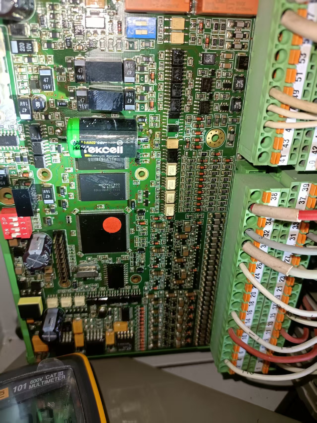
(2) Simultaneously measure the no-load voltage of the on-board Tekcell backup lithium battery. It is the reason that A depleted battery only results in loss of logs and parameters after power cut, and will not cause full-system breakdown.
2.1.2 Re-inspection and Tightening of Wiring Terminals
(1) Unplug and reinsert the green spring terminals on the right side,
(2) Retighten signal cables of transmitters and valve modules,
(3) And check terminals for oxidation, looseness, open circuits and damage.
(4) Found above item (1)-(3)in order
2.1.3 Independent Single-Loop Test of Peripheral Equipment
(1) Carry out closed-loop single-point tests for each peripheral device separately.
(2) Found the measuring point signals still fail to upload to the monitoring system after excluding faults of cables, transmitters and valve execution modules themselves,
(3) It can be determined that the fault converges to the channel circuit or main control operation unit of the IO main board.
2.2 In-depth Troubleshooting of Main Board Core Components
After completing peripheral inspection and confirming the fault is confined to the main board itself, conduct verification against above mentioned three typical CPU fault types respectively:
Fault Type 1: Complete Disorder of Control Logic (No Drainage Triggered at Over-Liquid Level, Unintended Shutdown Interlock Without Abnormalities)
(1) Signal Input Traceability Test: Use a multimeter to measure the 4 ~ 20mA analog quantity transmitted from the transmitter to the main board terminals. The measured value matches the actual liquid level inside the tank, proving the front-end collected signals are normal. However, drive commands issued by the CPU to valve modules conflict with preset interlock logic, indicating abnormal operation of the arithmetic unit.
(2) Parameter Reset Retest: Restore the DIP dial switch to factory default gears, recalibrate the liquid level interlock threshold for ballast tanks. The erroneous control behavior persists after power-on, eliminating misconfiguration of parameters.
(3) Firmware Replacement Test: Flash factory-compliant supporting firmware into the flash memory chip, while fault phenomena remain unchanged, ruling out damaged firmware files and confirming the arithmetic unit of the main control CPU is damaged.
Fault Type 2: No Response of the Entire Main Board (No Indicator Light On After Power-up, No Measuring Point Signals, Failed Interlock Protection)
(1) CPU Power Supply Pin Measurement: Measure the voltage of the chip power input pins by referencing PCB wiring. Found the power supply voltage is normal yet the chip outputs no signals at all, the internal power supply circuit of the chip is broken down. (If no input voltage is detected at the pins, reversely inspect front-end power supply inductors and MOS switching tubes.)
(2) Visual Inspection of Component Appearance: Check whether the chip surface is blackened, bulged, short-circuited at pins or severely corroded by salt spray. (If Obvious physical burn marks directly confirm hardware damage to the chip.)
(3) Cross-replacement Verification with Identical Board: Replace the original board with an intact IO main control board of the same specification in situ, restore wiring. The cabinet indicator light turns on normally, communication of all measuring points and valve interlock control recover fully, 100% confirming damage to the CPU chip of the original board.
Fault Type 3: Intermittent Crash Under High Temperature & Vibration (Temporary Recovery After Power Cycle, Recurring Repeatedly)
(1) Fault Simulation and Reproduction: Use a low-temperature hair dryer to heat partial areas of the main board, and press the CPU chip lightly with an insulating stick to simulate hull vibration. Communication interruption faults can be triggered artificially, most likely caused by virtual soldering of CPU pins or aging of the internal wafer of the chip.
(2) Pin Resoldering Verification: Use a constant-temperature electric soldering iron to resolder all CPU pins and remove oxide layers, then power on for trial operation:
Fault disappears after resoldering: Only oxidized virtual soldering at pins, with intact chip body;
Fault persists after resoldering: Internal semiconductor unit of the CPU is aged and expired.
Found fault persist after resoldering, confirm the CPU malfunction at last
Part 3 Fault Repair Scheme & Delivery Acceptance Test
3.1 Determination of Maintenance Scheme
After communication and evaluation with the ship’s duty crew, the optimal maintenance scheme was confirmed:
(1) Abandon on-site welding and repair of the single CPU chip; directly replace the whole IO main control board with a brand-new unit certified and compatible with marine survey standards. Complete point-by-point calibration and full-system joint commissioning of interlock logic after replacement, eliminating all faults completely.
(2) Scheme Explanation: Under the long-term high-vibration and high salt-spray operating conditions in the marine engine room, on-site manual chip welding lacks sufficient weather resistance, prone to secondary faults in later stages, which may trigger navigation safety hazards such as out-of-control ballast water and unexpected auxiliary engine shutdown. Therefore, full board replacement is a stable and compliant solution.
3.2 Three-Layer Delivery Acceptance Test
(1) Static Berth No-Load Test
Manually simulate high and low liquid level working conditions; the opening/closing logic of drainage valves fully matches preset interlock rules. No random offline measuring points or false alarms appear in the control cabinet.
(2) Dynamic Sailing Simulation Verification
Operate continuously under simulated wind and wave vibration as well as full-load high-temperature conditions of the engine room, with no intermittent crash or false interlock trigger.
(3) Power-off Durability Stability Test
Cut off the main power supply of the main board and stand by for 30 minutes. After power restoration, networking parameters and interlock thresholds are fully retained, and the whole automation system operates stably without drift.
Part 4 Comparison Table of Fault Characteristics for All Components on IO Main Board (For reference only)
Combined with the disassembly and maintenance experience of this case, we sort out typical fault manifestations of each core component on this model of IO main board, to facilitate quick fault location for engineers and maintenance personnel:
(1) Tekcell Backup Storage Battery
Fault Manifestation: After long-term power-off berthing at port, the battery self-discharges completely, failing to store operation logs and system configurations after power cut.
Maintenance Suggestion: Detect the voltage and internal resistance of the battery every 6 months. Replace with flame-retardant energy storage batteries compliant with marine regulations once loss thresholds are exceeded.
(2) Spansion Flash Memory Chip
(1) Failure to Save Parameters: After setting networking addresses and liquid level calibration parameters via dial switches, all configurations revert to factory defaults after power cycle.
(2) Loss of Fault Logs: Alarms are triggered by equipment, yet the monitoring system cannot retain historical fault records.
(3) Partial Interlock Function Loss: Basic liquid level collection works normally, while some customized interlock logics are missing (CPU operation function remains intact; only the storage unit is damaged).
(3) On-board Crystal Oscillator
Faults occur intermittently without complete paralysis of the main board. The system runs barely at room temperature, yet communication disconnection rises sharply under hull vibration or high engine room temperature. Replacing a crystal oscillator of matching specifications alone can fix the fault without damage to the CPU.
(4) DIP Dial Switch & Adjustable Potentiometer at Top Left
(1) DIP Dial Switch: Only a single channel communication measuring point goes offline while others function normally. Signals cut on and off during gear shifting due to poor contact from salt-spray oxidation on contacts.
(2) Adjustable Potentiometer: Fixed offset appears in measured liquid level and oil pressure values, which can be calibrated by fine-tuning the potentiometer knob without abnormal main control operation logic.
(5) SMD Resistors, Triodes, Power Inductors and Other Peripheral Components
Faults are limited to a single signal loop only: drift readings of a single transmitter or failure to drive a single valve, with all other measuring points running normally. Multimeter measurement shows component resistance and conduction parameters deviate from standard specifications. Replacing the corresponding small components can resolve the fault without damage to core CPU and flash memory chips.
Part 5 Write at the end
Looking back on the complete troubleshooting process of this case: starting from superficial signal fluctuation and offline measuring points, to finally locating damaged core chips on the IO main control board; ranging from routine inspection of external equipment to hardware-level fault diagnosis deep inside the system. All operations fall within the scope of marine automation maintenance.
Nowadays, marine automation equipment is iterating and upgrading rapidly with increasingly high system integration. Faults are no longer limited to simple damage of single devices, but mostly manifest as systematic disorder, continuously raising the technical difficulty and professional threshold of shore-based maintenance. This is the normal state of industrial development, and also the driving force encouraging all automation maintenance practitioners to pursue continuous progress.
No matter how marine electric control systems are updated or how complex faults become, our core maintenance logic never changes: the entire automation system is assembled from independent components following standardized logic and controlled by preset programs to operate. Mastering the basic functions of each component, understanding system control principles, evaluating the overall system performance first before pinpointing faulty single parts — this remains the invariable core thinking of marine automation maintenance.
Technical operation relies on accumulated experience, while fault judgment depends on systematic thinking frameworks. Equipment itself does not grow more complex; what we need to continuously upgrade and improve is the professional awareness, troubleshooting logic and practical operation capabilities of every relevant practitioner.
Deeply engaged in marine automation maintenance, we keep accumulating experience, continuous learning and on-site practical operation. Only in this way can we accurately judge, efficiently resolve and reliably deliver solutions when facing faults of increasingly sophisticated marine electric control systems.



 +8615005328513 (wechat ) +8613606393913 (Whatsapp)

 No. 8888, Huangshan Road, Huangdao District, Qingdao City, Shandong Province, China.